GENERAL INFORMATION
| Application | Indoor |
| Standard | IEC 61869-2 DIN VDE 0414/1 ANSI C57.13 |
| Operation temp. | -5°C…..+45°C |
| Test voltage | 3kV eff, 1 min. |
| Max. Operating voltage | Um ≤ 0,72kV |
| Rated frequency | 50/60Hz |
| Rated cont.thermal current | %120xIpr |
| Rated short time thermal current | Ith=60xIpr |
| Rated primary current | up to 5000 A |
| Class | 0,2S – 0,5S – 0,5 - 1 |
| Rated burden | 1 VA….30 VA |
Certificates
- ISO 9001-2008
- ISO 14000-2004
- ISO 18001-2008
Mainly are used where it is imposible or difficult to measure currents directly.
They are special configurations of transformers which transform the primary current into a (mostly) lower secondary current and which separete (galvanicaly) both circuits.
By means of the physical principle of saturation of the core material additional a protection of the secondary circuit from high currents produced in the event of system fault is enable.
Generally current transformers are distinguished for measuring purpose and protection purposes.
Instrument transformers are assigned for connection direct reading, writing and counting measuring equipment and protecting these additional from overcurrent.
Protection transformers are assigned for connecting plants protection equipment.
Fundamentally can be distinguished between single conductor current trasformers and wound primary current transformers.
The most important type of single conductor CT’s is the window type CT which is designed to be pushed onto the primary conductor.
Together with this conductor a special transformer with one primary turn is built.
The power performance of a current transformer depends on the transformation atio and on the cross-section of the iron core.
If the primary current is too low a single conductor CT with a higher transmission is to be used.
To simulate the higher current (corresponding to the higher transmission) the primary conductor is put through the single conductor CT for a several times.
In this way a wound primary current transformer is constructed.
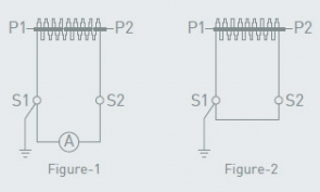
The marking of the primary terminals is P1 (K) and P2 (L), and secondary S1 (k) and S2 (l).
The polarity has to be done in that way that the direction of the energy goes from P1 (K) to P2 (L).
Alce current transformers correspond to the international standards such as IEC 60044-1, DIN, VDE 0414T,1 ANSI C57.13, etc
Secondary terminals
One of the secondary terminals should be earthed for safety. Secondary circuit of a current transformer must not be operated with an open circuit.
It should be connected measuring devices before application of primary connection as seen in figure-1.
The secondary winding of current transformer which will not be used must always be short-circuited and earthed as seen in figure-2.


