

| CAPACITIVE DIVIDER INSULATORS
Necessary information for ordering: Application |
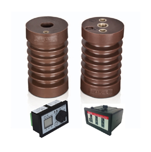 |
Construction
Indoor voltage divider insulators are epoxy cast resin.
The main dimensions and mechanical requirements are in accordance with DIN 48136.
Tests
In addition to the tests applied to the standard insulators according to
VDE 0441 part 3 (1984),
IEC 60660-1999 following routine tests are performed:
- Power-frequency withstand voltage test (dry)
- Partial discharge measurement
- Capacitance test
Capacitive voltage indicating system for medium voltage
Capacitance-coupled voltage indication system
The voltage indication system consists essentially of a capacitive voltage divider between a conductor L and earth. Moreover,
the system includes an indicator for the detection of voltage and a surge arrester for protection purposes.
Function
Voltage division occurs due to the capacitive values of C1 and C2. According to IEC 61243-5 the indication should start in between 10% of the read voltage of the system.
For that reason, the capacitance values are adjusted in accordance within this range so that the indication starts.
Up to10% of the rated voltage ,there shall beno indication. Under any circumstance above 45% of the rated voltage the indication shall be ''ON''.
The presence of voltage is indicate separately and independently for each phase conductor. The system operates without a battery or auxiliary supply.
The energy required for the system is being drawn from the high voltage system
(CAPDIS system may require auxiliary power for some additional functions depending on the application).
Shock hazard protection
Voltage indication system does not present any risk during normal or disturbed operation. During normal operation,
the voltage divider capacitance C1 limits the currents to less than 100μ±A.